Some RS485 devices come with optical isolators installed (also called Galvanic isolation) on the RS485 port, and some don't.
It is important to know how to wire devices on an RS485 network, especially when a non opto-isolated device is present.
So, how do I wire my RS485 devices?
No matter the devices, it is always good on real site installation to use a shielded cable, with 18-22AWG wiring and the shield connected ONLY to one end of the line.
The shield works as a "drain" for any noise that could be picked up by the RS485 network and "drain" it to ground.
The RS485 network is wrongly referred to as a "2 wires plus shield" network. It is not.
The 2 wires are sometimes referred as "+" and "-" instead of "A" and "B", making the user think that 2 wires is all you need to make it work. But these are signal wires and the network always requires a return path.
The EIA/RS-485 standard states:
"Proper operation of the generator and receiver circuits requires the presence of a signal return path between the circuit grounds of the equipment at each end of the interconnection. The circuit reference may be established by a third conductor connecting the common leads of devices, or it may be established by connections in each using equipment to an earth reference."
When the devices on the RS485 network are all opto-isolated, it is common practice to use a 2 wire twisted pair shielded cable, where the shield is used also as "return path" (ground) and is connected to each device like shown here:
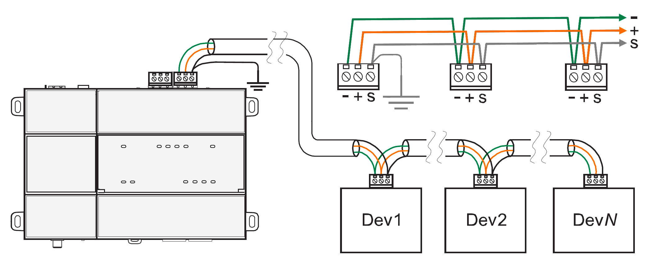
This works and is sometimes also recommended by many vendors. Why? Even without the shield, the RS485 network is quite robust. It gets away most of the time with this configuration, with the shield draining noise and providing the ground reference at the same time.
But it does not work ALL the time.
With noisy environments (our sites?) using the shield as ground is not always the most effective solution.
And even worse, if you have a non opto-isolated device installed on that network, any noise could "drain" to ground through the device itself instead of flowing through the ground terminal at the end of the line, damaging the device in the process!
The ideal RS485 network requires a dedicated wire for ground.
Also, when some devices on the RS485 are NOT opto-isolated, the third wire becomes essential to avoid the units being damaged.
In this configuration, you can see that the shield is still there and just simply daisy-chained on each cable junction, then connected to ground only on one end like shown here:
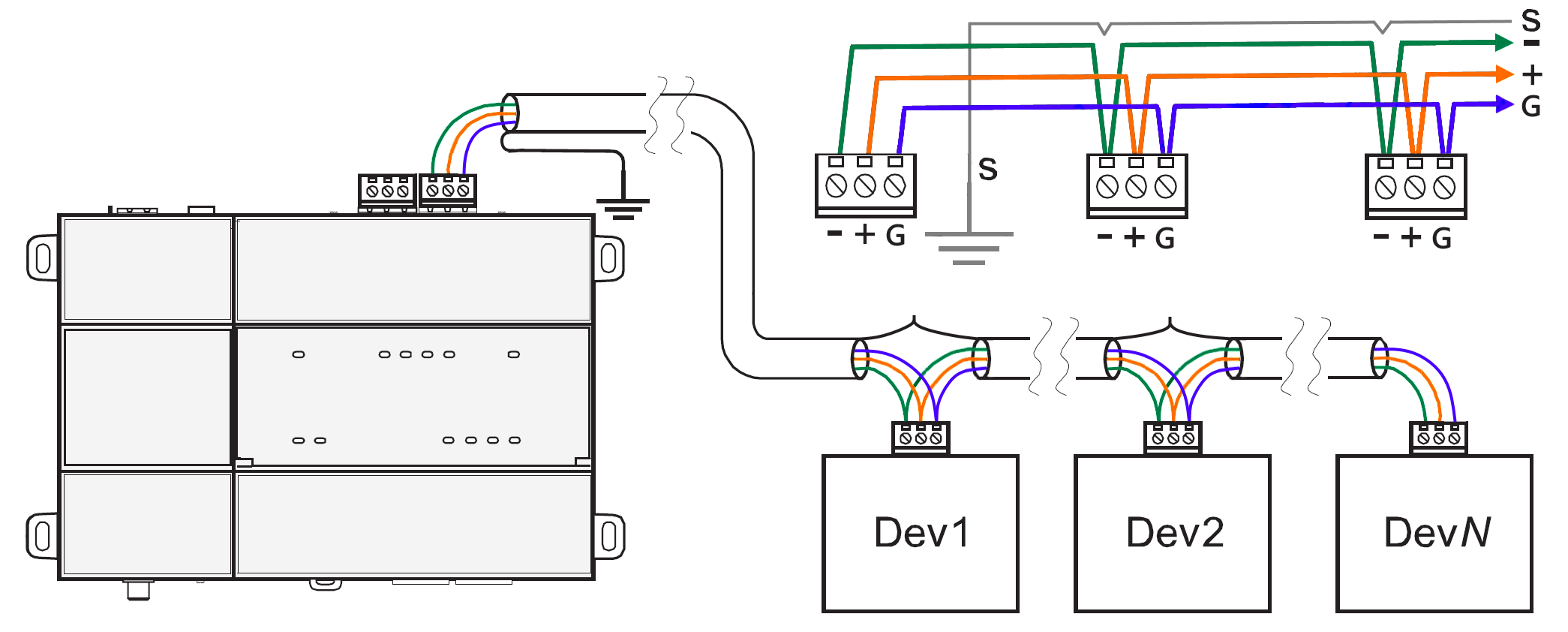
The cable recommended in this type of connection is the Belden 9842, which has 2 twisted pairs. A pair will be used for "+" and "-" (or "A" and "B"), one of the wires of the second pair will be used as "ground" and the fourth wire will be not-used.
Check out also our article about BIAS and TERMINATION resistors. Combined with the right cables, they are going to guarantee the creation of stable and functional RS485 networks.
https://know.innon.com/bias-termination-rs485-network
From Innon, here is a list of devices that are NOT opto-isolated and will require the 3 wires plus shield configuration:
- iSMA MIX series (all)
- iSMA MINI series (all)
- iSMA FCU controllers (all)
- iSMA AAC20 controllers (all)
- iSMA MG-IP converter