Most of the devices we sell need power to work, many of them with a nominal power requirement of 24Vdc or 24Vac.
But how do you ensure such power supply is wired and sized properly for your devices?
Here are a few things that we always advise to check when powering our devices.
Voltage
The modules are designed to work with a nominal voltage and a range around it. For example, most of our iSMA devices are designed to work with 24V (ac or dc) and allow a range of ± 20%, making the overall usable power supply voltage between 20V and 28V.
This is to account for potential spikes in the mains power, which when using an AC transformer will translate into spikes on the 24Vac line as well.
24Vdc Power Supply Unit are not as affected by voltage spikes on the mains.
A common issue is the use of AC transformers that sometimes provide a in-load measured output above 24Vac, like 26Vac. Many times this happens with the use of 220Vac/24Vac transformers connected to mains at 230Vac and higher.
Remember to measure the in-load output of your transformer to make sure it is as close as possible to 24V!
Despite the in-load voltage being within tolerance, a 26V in-load output allows for a much narrower margin for voltage spikes. So when a spike occurs, the device can be potentially damaged finding voltages exceeding the design range.
Connect G0 to earth
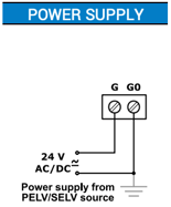
Remember to connect the "G0" terminal of each controller and the "G0" terminal of the secondary side of the transformer to earth, to avoid different potentials on the reference of any controller.
Check the device installation instruction document for more information. You can find them all on our support website support.innon.com
Check if the device is optoisolated and connect the RS485 accordingly
Most of the iSMA RS485 devices are NOT optoisolated. This means a specific RS485 cable is required (Belden 9842), with the shield disconnected from "G0". The shield will still need to be connected to earth on one end of the line.
Check out this article about how to wire non optoisolated devices in detail https://know.innon.com/knowledge/howtowire-non-optoisolated
Connecting a normal twisted pair plus shield to non optoisolated devices is most probably going to introduce unwanted noise (unwanted extra voltage) on the RS485 "G0" terminal that can potentially damage the device.
Diesel generators? Avoid the spikes!
If the site has diesel generators we know they spike when a changeover happens.
Such spikes will be transferred to the low voltage 24Vac network, damaging your controllers.
A "surge protector" can help with this, filtering out the spikes.
We recommend to use a single phase surge protector, type SPD class 2.
Using a UPS? Not all UPS will protect you!
Using a UPS especially to avoid network noise and voltage spikes might not work. The main objective of a UPS is to guarantee power when a power loss occurs.
In fact, only expensive "online" UPSs would protect from noises on the mains, creating a clean "new" signal on their output. Most common UPSs are "offline", which means that they just pass through the mains power when there is no need for the UPS to engage
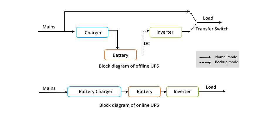
Check with the manufacturer of your UPS to verify if it is effective against voltage spikes, as many budget "offline" UPSs are not.
Don't double up wires on actuators
If you happen to be wiring a 3 wires actuator with 4 core cable (2 core for +/- 24V and 1 core for 0-10V feedback), do not use the 4th available wire to "double up"s (such as for G0 going out to the actuators).
Doing so picks up voltage along the way and adds up to the G0 of the PSU increasing the chances for the module to get higher voltage than permitted.
Use only the wires you need.
Check the power requirements of each device and add them up
Each device has an amount of power required to work.
Such power is expressed in VA for AC power supply, or in W for DC power supply.
Verify the power requirement of each connected device (see the installation instruction on our support website support.innon.com) and make sure the Power Supply Unit or Transformer you are using is providing enough power to match or preferably exceed the total power consumption of the connected controllers.