Connecting and configuring the device
1) Power supply
You can use 20Vac to 28Vac or 20Vdc to 28Vdc
The power required (in VA when powered with 24Vac and in W when powered with 24Vdc) depends on the device model and can be found on the installation instructions enclosed with the device, or online on our support website HERE for the MIX series, and HERE for the MINI series.
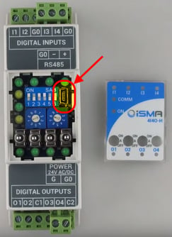
The device can be powered from the USB mini port situated behind the front panel, next to the configuration dip-switches (should be used only for the device configuration).
Check our article about best practice and recommendations on powering our devices HERE
2) RS485 serial port
The iSMA MIX and MINI series are non-optoisolated devices. More information on this can be found on our article about non-optoisolated device wiring HERE
Recommended cable from manufacturer is Belden 9842 (tech sheet).
Like on any RS485 network, correct network terminations will be required. Please follow our advice on the use of bias and termination resistors available HERE
3) Connecting a PC to the device
The USB mini port in front of all iSMA MIX and MINI devices allows to connect them to a PC for firmware update and configuration.
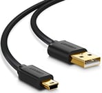
The cable required is a USB mini to USB A. The cable needs to be a power and data cable.
The software required on your PC is the iSMA Configurator. You can find the iSMA Configurator and related documentation HERE
4) Verify and update the firmware
This is very important: the first thing to do is to check and update the device firmware!
Detailed instructions on how to do this are available in the iSMA Configurator manual HERE on chapter 3.1
We have also a useful video showing the steps here below
5) You must restore the device default settings
Restoring the defaults after updating the firmware is recommended.
- Turn off the power supply
- Set dip-switch number 6 to ON
- Turn on the power supply; power LED blinks
- Set now the dip-switch number 6 to OFF to restore the default settings. To cancel the
reset, turn off the power and set the dip-switch number 6 to OFF
See here below a video where we run through the procedure
6) Setting up the communication protocol
The protocol can be configured using the dip-switches and rotary switches or via the iSMA Configurator software. Note: Setting the dip-switches and rotary switches will take priority over any settings within the software.
To know more about how to set the device up using the dip-switches and rotary switches, and to know how that works with the Tridium Niagara framework, have a look
Please consult the Device manual for a full list of the data points available and more information about the protocol use.
7) Setting up the inputs/outputs type
The setup of the type of inputs (sensor, resistor, voltage, etc) and outputs can be done either using Modbus/BACnet configuration points, or simply via the iSMA Configurator software.
If you have a module enabled for IP communication, the setup of the inputs and outputs can be done also through the web interface of the device
Additional information
This guide applies to the following products
iSMA MIX series:
iSMA-B-MIX18, iSMA-B-MIX38
iSMA MINI series:
iSMA-B-8I, iSMA-B-8U, iSMA-B-4I4O-H, iSMA-B-4U4O-H, iSMA-B-4U4A-H, iSMA-B-4O-H, iSMA-B-4TO-H
Where to find the documentation about this product
Data sheets, manuals, installation manuals, device pictures, CAD drawings and certificates can be found on our support website support.innon.com:
What is inside the box
Inside the box you will find:
- The iSMA I/O device
- All the connectors (5.08mm MSTB screw down terminal blocks)
- 200 ohm resistors set to connect 4-20mA signals to the Universal Inputs (only for devices provided with Universal Inputs)
- The installation instructions