A 4-20mA sensor provides a regulated current signal output that varies between a minimum of 4mA to a maximum of 20mA, giving the possibility of identifying if the sensor is broken or disconnected (current goes below 4mA, the minimum) and usually allowing for longer distances between the sensor and the input reading. The resistance of the cable has less negative effects on this sensors, as a few ohms of cable resistance will cause a small voltage drop, but will not be affecting the precision of the reading as the current will remain perfectly controlled (note: check the sensor specs to verify the maximum allowed signal resistance).
A controller or I/O module that can be natively configured to take a 4-20mA signal input will basically short circuit the input to 0V and measure the current flowing, a bit like your multi meter when configured to read amps.
See picture here below:
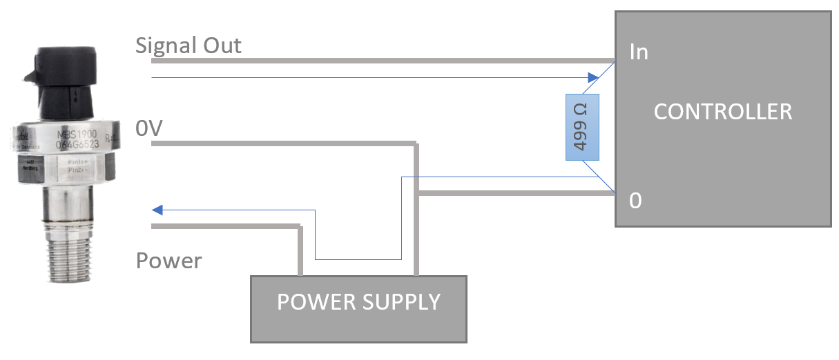
A few controllers and I/O devices cannot accept 4-20mA to be connected directly. To overcome this limitation, the idea is to set the input as a voltage reader (0-10V) and put a 500 ohm resistor between the input and the 0V reference.
The Input configured as 0-10V is an open circuit, so the current will flow across the resistor, creating a voltage drop between In and 0V. The voltage drop is going to vary between 2V at 4mA and 10V at 20mA, like shown below:
What is the problem with this method?
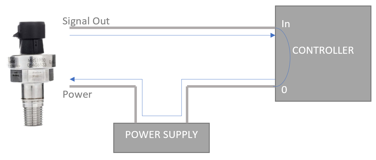
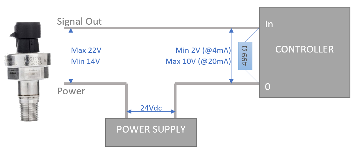
Well, if you are using a sensor that doesn't have a 0V reference third wire like the one displayed in this example (usually referred as "2 wires sensors" or "loop powered sensors"), you will clearly see below the issue: when the output signal increases, up to its maximum 20mA, the voltage drop across the resistor will increase as well up to 10V. The reference of the sensor is not 0V anymore, but will vary between 2V and 10V, creating a voltage drop between the sensor inputs "Power" and "Signal out" that can go down to 14V.
The sensor specifications will require a certain minimum voltage for the sensor to work, and most likely a 24V sensor will not be able to work with a voltage as low as 14V.
See the picture below:
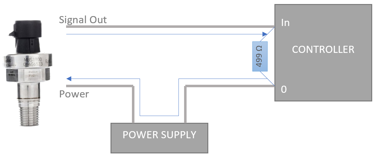
This is the reason why manufacturers of controllers that do not support 4-20mA natively and need the resistor to measure the signal as a voltage drop instead of reading the current directly, will require the sensor connected to be a 3 wires sensor, so that there is a permanent 0V reference and the sensor power section is stabilized at 24Vdc.
See below: