We need a bit of theory here to understand why an RS485 network needs Bias resistors and Termination resistors in the first place.
Don't worry, I will try to keep it as simple as I possibly can.
Termination resistors
Transmission line effects often present a problem in data communication networks. These problems include reflections and signal attenuation.
When a voltage is first applied to an RS485 line, current flows through the line (even if the line wires are open). Shortly after reaching the end of the line, the current settles to a final value determined by the series resistances in line, the voltage applied, and termination. The line sees reflected voltages as the current settles if the initial and final currents vary, resulting in possible data integrity issues.
If the data rate is low or cables are short, termination may be unnecessary. As data rates and/or cable lengths increase, which is most cases, termination becomes mandatory.
To eliminate the presence of reflections from the end of the cable, it must be terminated at both ends with a resistor across the line (between + and -), in accordance with its characteristic impedance. Both ends must be terminated since the direction of propagation is bidirectional.
In case of an RS485 twisted pair cable this termination is typically between 120 and 130 Ω.
Here is a simple schematic of how the end of the lines should be terminated:
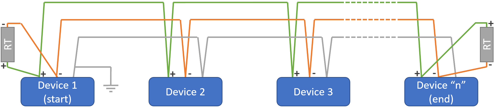
"RT" is the 120 Ω termination resistor.
"Device 1" on a Modbus network is the Master device initiating communication.
Bias resistors
With RS485 networks, there are periods of time when no driver is actively driving the bus. On a Master-Slave network this would correspond to potential times when the Master is not transmitting and the slaves have finished responding to any command.
This state is also called "tri-state mode".
During this time, the termination resistors collapse the differential bus voltage to 0V, which is an undefined input level for many RS485 receivers. Faced with this undefined input, a receiver might output the wrong logic state or worse yet, it might oscillate. The oscillation may be interpreted as an endless stream of message start bits, causing the controller to waste valuable bandwidth trying to service these phantom messages. Fail-safe bus biasing is one way to alleviate this problem.
The objective of biasing is to make sure that the RS485 line remains in a known, non-fluctuating state when no devices are transmitting. Biasing the entire network requires a single pair of resistors: a pull-up resistor to +5V attached to the "+" signal line, and a pull-down resistor to ground attached to the "-" signal line.
See the schematic here below which explains how biasing is achieved:
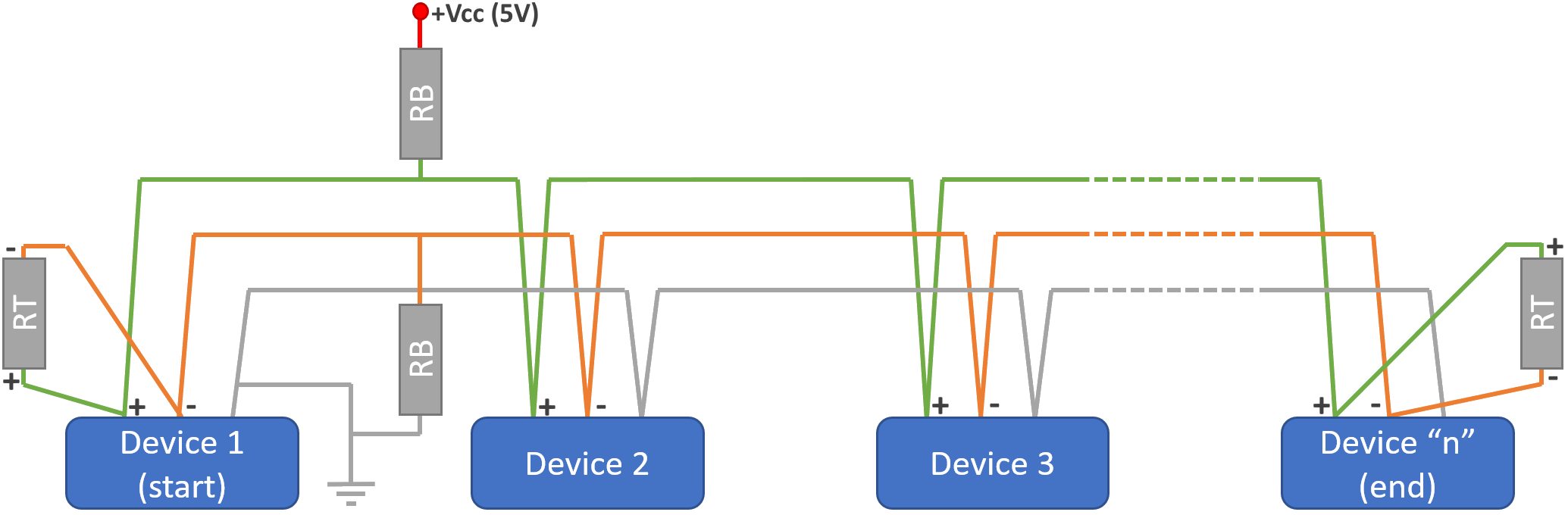
The "RB" going between "-" and "earth" is the "pull-down" resistor, the "RB" going between "+" and "+Vcc(5V)" is the "pull-up" resistor.
It might look a bit more complicated to connect the bias resistors to your network, but I have good news for you: most of our primary controllers can enable biasing with just a change of a switch position. And you need only 1 device in the network to do that.
Keep reading to know how!
Here below is a list of devices sold by Innon that allow the user to setup the termination and bias without having to install additional resistors
How to set termination and bias on a Tridium JACE8000 controller
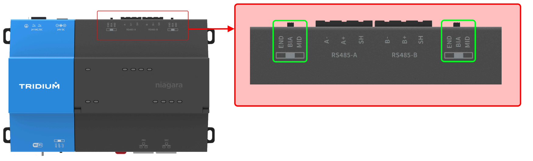
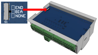
The JACE8000 controller has a 3 position switch that allows to configure the termination and bias without the need of physically connecting the resistors.
The switch positions are:
- END. Usually selected when the JACE8000 is connected at one end of the RS485 line. This position enables both the 150 Ω termination resistor AND the 562 Ω bias resistors (no other device on this line should have the bias enabled)
- BIA. Usually selected when the JACE8000 is connected in the middle of an RS485 line that hasn't got any device providing the bias. This position enables ONLY the 2.7 kΩ bias resistors
- MID. Usually selected when the JACE8000 is connected in the middle of an RS485 line that has got a device already providing the bias. This position doesn't enable ANY resistor.
The setting for the RS485 ports can be found next to each RS485 port on the controller as shown
How to set termination and bias on an iSMA MAC controller
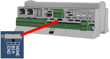
The MAC controller has a 3 position switch that allows to configure the termination and bias without the need of physically connecting the resistors.
The switch positions are:
- END. Usually selected when the MAC is connected at one end of the RS485 line. This position enables both the 120 Ω termination resistor AND the 680 Ω bias resistors (no other device on this line should have the bias enabled)
- BIA. Usually selected when the MAC is connected in the middle of an RS485 line that hasn't got any device providing the bias. This position enables ONLY the 680 Ω bias resistors
- NONE. Usually selected when the MAC is connected in the middle of an RS485 line that has got a device already providing the bias. This position doesn't enable ANY resistor.
The setting for the main RS485 port can be found on the back of the controller
The setting for the secondary RS485 port (if present) can be found just below the port itself
How to set termination and bias on a SierraMonitor Bacnet router
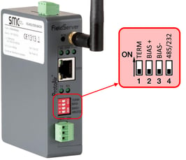
The Bacnet routers are provided with a set of dip-switches that allow to configure the termination and bias without the need of physically connecting the resistors.
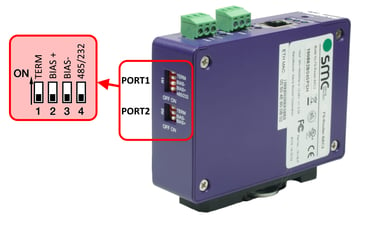
There are a total of 4 dip-switches
- TERM. Set this dip-switch "ON" if you want to enable the termination resistor, "OFF" if you want to disable it
- BIAS+. Together with BIAS-, these should both be "ON" if you want to enable the bias resistors. Both should be "OFF" if you want to disable the bias resistors
- BIAS-. Together with BIAS+, these should both be "ON" if you want to enable the bias resistors. Both should be "OFF" if you want to disable the bias resistors
- 485/232. If you are using an RS485 network, this dip-switch should be left to the "OFF" position
Where to find the configuration dip-switches on the Wi-Fi version of the router (only 1 RS485 port)
Where to find the configuration dip-switches on the regular version of the router (2 separate RS485 ports)