Our lineup of wireless sensors provided by Enless includes the Wireless M-BUS range, which is used for local installations where all sensors report to a gateway device that allows to read data from any connected sensor using a serial Modbus connection (RS232 or RS485).
The setup requires a process of "binding" between the sensors and the gateway (please refer to the installation manuals available HERE), achieved through the F.C.T. software running on a Windows PC. Important: remember ALWAYS to save your configuration file and keep a copy of the file for future modifications.
Towards the end of the process a Modbus Table is available, providing the Modbus data point addresses for each sensor configured during the setup process.
You might notice the addresses are by default starting as 31xxx. This could lead to thinking that the registers are Input Register and that the address is in "Modbus notation", but that would be incorrect. The data points are in fact all Holding Registers (function code 03) and the address notation is decimal.
This sometimes creates some confusion and many customers fall into the 31xxx address "trap".
When reading using a Tridium Niagara controller, remember to add your data selecting "NumericWritable" type and that the address is in "decimal" format.
See the screenshot here below:
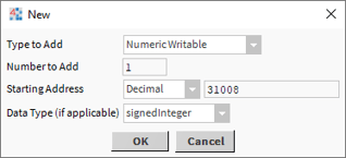
Niagara will automatically use a Holding Register when configuring a NumericWritable.
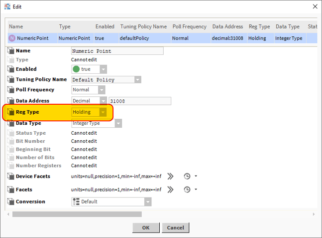
If by any means you decide to use a "NumericPoint" instead (effectively adding a read only point), make sure you change the register type to "Holding", as the default selection for "NumericPoint" is "Input register", which would not work