Many of your control devices, powered sensors etc will allow to use either DC or AC to power them up.
The electronics inside such devices though will always work with DC power internally. A rectifier is embedded within the device power circuit to convert an eventual AC power input to the required DC internal power.
Rectifiers though are not all the same, there are mainly 2 types:
- Half-Wave rectifiers, cheaper and more inefficient option, usually adopted by devices where minor cost differences have large impact
- Full-Wave rectifiers, more expensive and more efficient, usually adopted by main controls devices
Having a mix of half-wave and full-wave rectifier devices powered by the same AC transformer could lead to trouble.
As soon as a "controls" ground connection (network, I/O...) is linked between these devices, you are probably going to get some of them damaged. This is the reason why many manufacturers recommend to use separate transformers for each control device.
Below in this article we are going to explain in more details the differences between the 2 rectifiers and we will try to guide you through the potential issues you might face.
DC power supplies are not affected by this issue, but getting the right polarity (+ and -) is usually even more important on half-wave rectifier devices: connecting the power the wrong way around will not work and potentially damage the device.
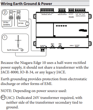
Some examples of devices where the issue is highlighted straight from the manufacturer documentation include the Tridium EDGE10 controller: a cheap way to get Niagara embedded in a robust solution designed as a scalable and cheap control for edge devices, this controller does not include a full-wave rectifier but an half-wave one. On the wiring instructions this can be seen:
Half-wave and Full-wave rectifier, what is the difference?
Half-wave rectifier
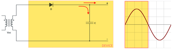
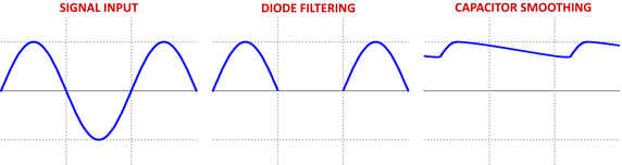
The half-wave rectifier is basically a filter that lets only the positive part of the wave to pass.
Looking at the images below, we can see that the diode "D" will let the positive wave to pass. The filter capacitor can charge during this transient and current flows directly also to the device electronics.
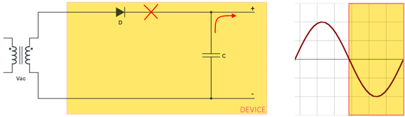
When going through the negative transient, the diode stops the current flow from the external transformer. The filter capacitor discharges the stored energy to the device electronics.
Full-wave rectifier
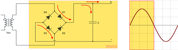
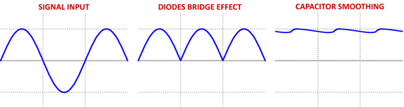
The full-wave rectifier works on a similar principle, but a bridge of diodes allows to use both the positive and the negative transients of the sine wave, effectively transforming the negative transient into another positive one internally.
On the positive transient, diode D1 allows flow through. The current energizes the filter capacitor and the device electronics. Diode D3 then allows the circuit to close back to the transformer.
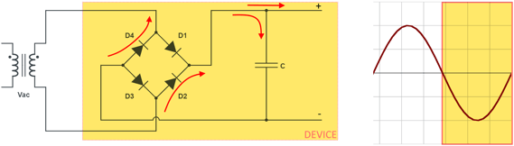
On the negative transient, diode D2 allows flow through, in exactly the same "positive" direction of the positive transient. The current energizes the filter capacitor and the device electronics. Diode D4 then allows the circuit to close back to the transformer.
When can I have a problem?
Let say that in general it is safer to use separate transformers for devices implementing different types of internal circuits.
But if you have a full-wave rectifier unit exposing to some control outputs (serial bus, common I/O connectors etc) the DC converted layer, you might want to be extra careful when sharing power supplies or on how you ground things.
Let's have a look at 2 examples I just made for this.
Example 1: grounding everything.
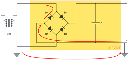
Check always the device documentation on what should be put to ground and what not. Let say that you have the device below, a full-wave rectifier device with the rectified common "-" also being available on the outputs. If you were grounding that and also the secondary side of the transformer, like it would be perfectly normal to do with devices such as the iSMA range, you might get a loop that would short the transformer on the negative wave transients through diode D4:
Example 2: mixed devices using the same transformer.
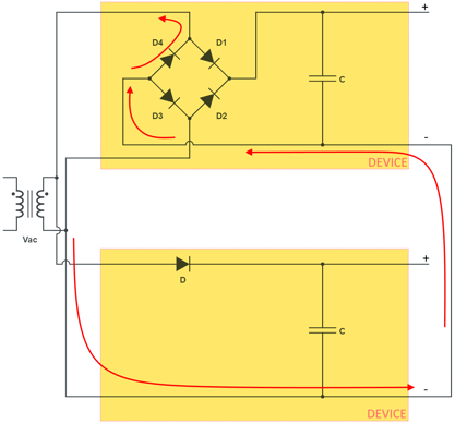
Let say you have an EDGE10 controller using the half-wave rectifier (device at the bottom) and a generic full-wave device (on the top), and both can be powered with 24Vac.
You decide to use the same transformer 24Vac to power both of them. If the full-wave rectifier device on the top exposes pins sharing the rectified common "-" and you plan to connect it with the "-" of a half-wave rectifier device, the 2 will close a loop that will short circuit through the diode D4 on negative wave transients:
What are common signs of this problem
- Fuses blowing as soon as you power up the system
- Diode shorting the transformer (D4) fails open, damaging the device
- Diode shorting the transformer (D4) fails shorted damaging multiple devices
- Because of the diode failing, you might notice the "burning" on the circuit board of the affected device, most probably near the power connector where the power management circuits should be, with maybe a black stain around the failed rectifier
In conclusion
Manufacturers might recommend to use separate transformers (see the Jace mounting doc HERE and the EDGE10 mounting doc HERE) and they will give you indications on how to properly ground the device. It is our recommendation to carefully follow the manufacturer guidance to avoid any issue.
If you plan on diverting from the manufacturer guidance you are basically taking responsibility for any risk involved, so it is important to consider all the information provided in this article to make a more careful decision before proceeding.
This means that you could carefully consider sharing the same transformer only if:
- You are powering the exact same devices
- You know for sure that different devices share the exact same type of rectifier
- There is not way to create a short circuit, for example knowing the common points are isolated (ie opto isolated serial ports) or are not connected at all. Be aware that in some cases even a simple grounded secondary side of the transformer can easily lead to a short circuit as mentioned in the examples above