If you would like to have an overview about what you can do with Modbus and Teltonika, check our main article HERE
Configure Modbus TCP slave devices
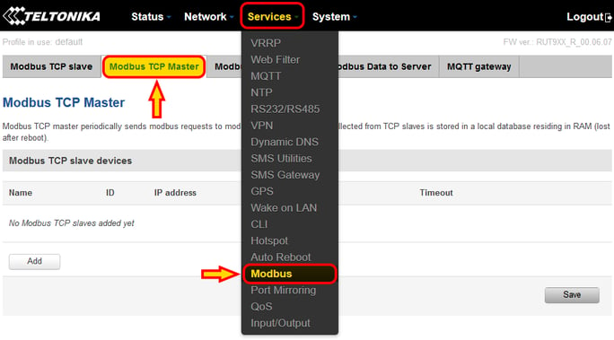
We need to open the Modbus TCP Master driver page, available within "Services - Modbus" and then selecting the tab "Modbus TCP Master"
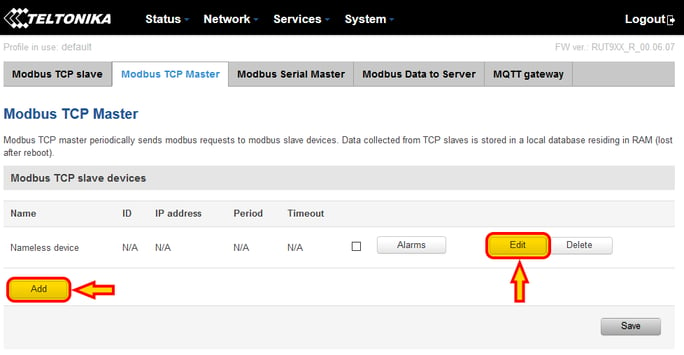
Pressing "Add" there, a new "nameless" device is created. We can press "Edit" to configure it
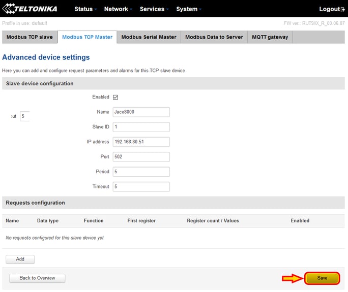
From the configuration page, the device settings can be adjusted giving the device a name, the Modbus ID, the IP address, the port (default on Modbus TCP is usually 502), the period, which is the frequency for the requests we are going to add below in seconds, and the timeout to declare a device offline.
Once all is configured, we can "Save" the configuration
Note that the save process takes a few seconds and will take you back to the Modbus TCP Master page. Press "Edit" again.
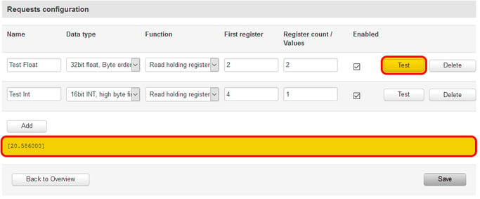
Using the button "Add" highlighted here below, I can add my Modbus data requests.
Why would I add requests? Requests are not used for basic strategies of any sort. The main reason to add request would be to push them using the MQTT client called "Modbus Data To Server" explained HERE.
If you want to see how to create basic logic instead, keep reading, we will need to use the "Alarms" button
If you are used to Tridium, note that "register 2" corresponds to "decimal 1" in Tridium, "register 4" to "decimal 3" and so on
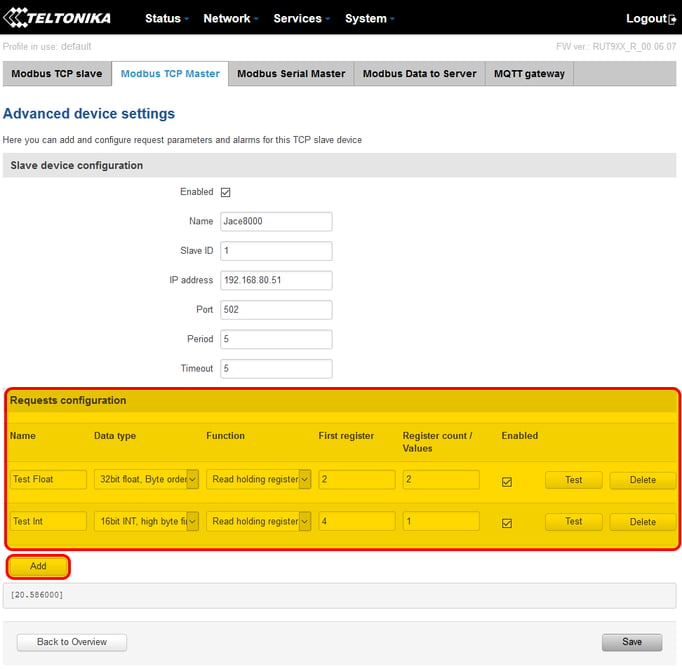
Using the "Test" button, I can verify that the specific data is read correctly. The response data is shown on the part just below the "Add" button
Ok, but how do we add data that triggers a basic function, like sending a command to another Modbus Slave device or control a Teltonika physical output?
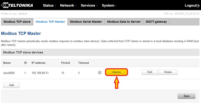
To achieve that we need to go back to the main Modbus TCP Master page, and on the device we want to read press the "Alarms" button
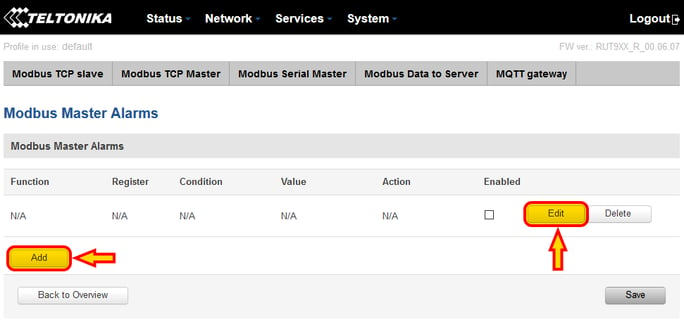
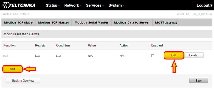
From the Alarms configuration page, we can press the "Add" button to add a new empty function, then "Edit" on the newly created function line
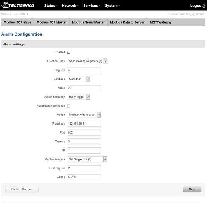
Here is where I can configure my basic function. The function starts with a read command usually, and a condition on the data you read (like reading a temperature and check if the value is greater than 20 degC to trigger the action, for example).
The "Action" then defines whether you want to send a write command to another Modbus Device (or the same device), drive a digital output, send an SMS...
In the example below, I am showing how I am reading from my Jace register decimal 3 (register 4) and if the value is greater than 20, I will write value "true" to the coil address decimal 1 (register 2) on the same jace with IP 192.168.80.51 and Modbus ID 1.
Note that with digital coils Teltonika identifies value "false" with "0" and "true" with "65280".
Note also that this function will only set my coil to "true". If I want to set my coil back to "false" when the temperature value goes below 20 degC, I will need another alarm function dedicated to setting the coil back to "false".
If you want to know more about the meaning of each individual setting, please consult the online manual HERE
Configure Modbus RS485 slave devices (RUT955 only)
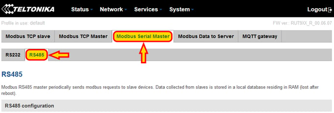
Like for Modbus TCP, the Modbus RS485 Master part will be available under "Services - Modbus", selecting the tab "Modbus Serial Master" and the sub-tab "RS485"
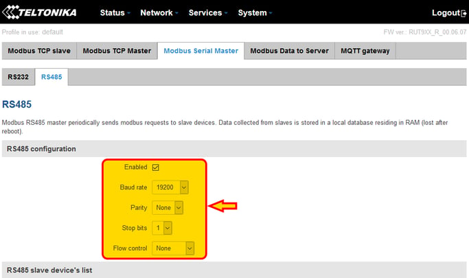
The network will need to be enabled with the dedicated "Enable" check. NOTE: if you use the RS485 to TCP gateway, this network needs to be disabled!
We can configure the port baud rate and network settings
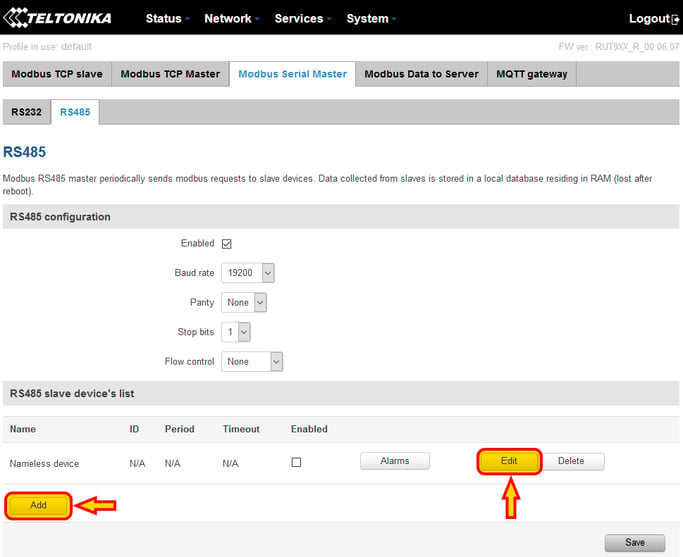
Once the network is configured, everything else works pretty much the same way as the Modbus TCP Master.
We can press the "Add" button and then "Edit" the newly created device
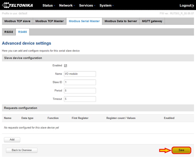
On the edit window, we can then configure the Modbus slave device, enabling it, giving it a name, setting up the Modbus ID (the address), the period, which is the time interval between Modbus commands and the timeout to detect the slave device being offline.
Then press "Save"
Note that the save process takes a few seconds and will take you back to the Modbus RS485 Master page.
Now, would I add "Requests" in the RS485 configuration? Probably not. The main scope I found for using "Requests" it is to push data over MQTT, but such feature is available only through the Modbus TCP Master driver, so there is no use here.
If you want to push data over MQTT from an RS485 device, check the chapter below, where using the RS485 to TCP gateway we can bypass this limitation.
So with this being said, using the RS485 driver makes sense if you want to run logic using the "Alarms". We need to press the "Alarms" button on the device then
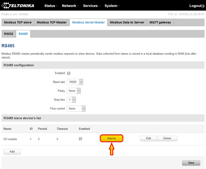
Once I am inside the Alarms page, I can "Add" a new basic function and then press "Edit" to configure it
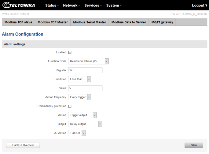
You can refer to the Modbus TCP Master chapter above example as well as they basically work the same way, but in this specific example I am reading an I/O device analog input, and if the value is less than 5 I close a physical relay output on the Teltonika.
Configure Modbus RS485 slave devices through the internal RS485 to TCP Gateway (RUT955 only)
First of all, why would you do this? To use it together with the Modbus TCP Master within Teltonika, if you are using the MQTT client to push Modbus data to MQTT and you want to push data coming from the RS485 network.
The MQTT client in fact does not work directly with data coming from the internal RS485 Teltonika driver, so a work around is to enable the RS485 to TCP gateway, and then read the RS485 slaves using the Teltonika Modbus TCP driver and "poll" the local IP address 127.0.0.1 (also called "localhost").
Check the dedicated article HERE to see how the gateway function is enabled.
Check the dedicated article HERE to see how to use the Modbus to MQTT function.
Remember that with the gateway enabled, the internal Modbus RS485 driver (the one in the chapter just above) should be disabled to avoid network clashes!