If you would like to have an overview about what you can do with Modbus and Teltonika, check our main article HERE
Configure the local MQTT broker
The Teltonika router can be used also as a local MQTT broker. MQTT clients can publish data directly to an MQTT broker sitting in the cloud, but sometimes using a local MQTT broker helps. For example, a local MQTT broker can ease communication between local devices using MQTT locally. Also, a local MQTT broker can work as a "bridge", collecting all the local data from local MQTT clients and then transferring them to a remote MQTT broker. The bridge configuration can be bidirectional.
In this example we are going to enable the local MQTT broker more to test the "Modbus Data to Server" and "MQTT Gateway" functions, to make our life easier.
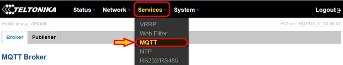
To enable the local MQTT broker we start from "Services - MQTT"
We are not going into the details on this topic. If you want to know more about the configurations on MQTT for Teltonika, please refer to the Manual.
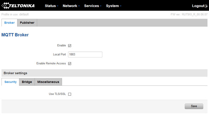
We are going to only enable the local broker, using the standard port 1883 and without using any security level
Get Modbus read data published to an MQTT broker using “Modbus Data to Server”
You might want to start first configuring the Modbus Slave devices and the data you want to read and publish over MQTT.
See the full article on how to configure slave devices and data over Modbus TCP and RS485 direct HERE
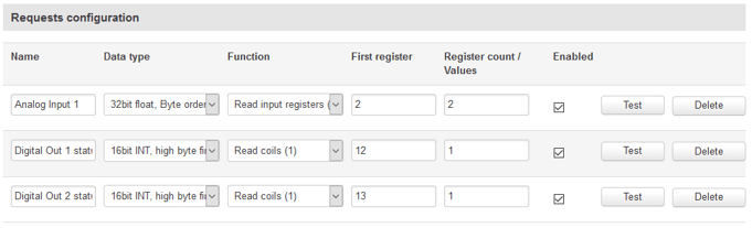
All the points added to the "Request Configuration" section of your Modbus devices will be available to be pushed over MQTT.
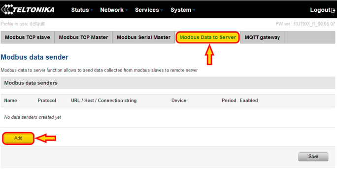
We start by getting to the "Modbus Data to Server" page, from the menu "Services - Modbus", then tab "Modbus Data to Server"
We can add our first data set to push over MQTT using the "Add" button
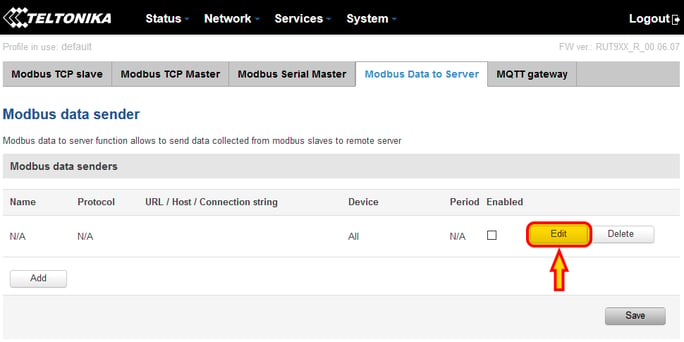
The first empty data set entry is created. We can edit it using the button "Edit"
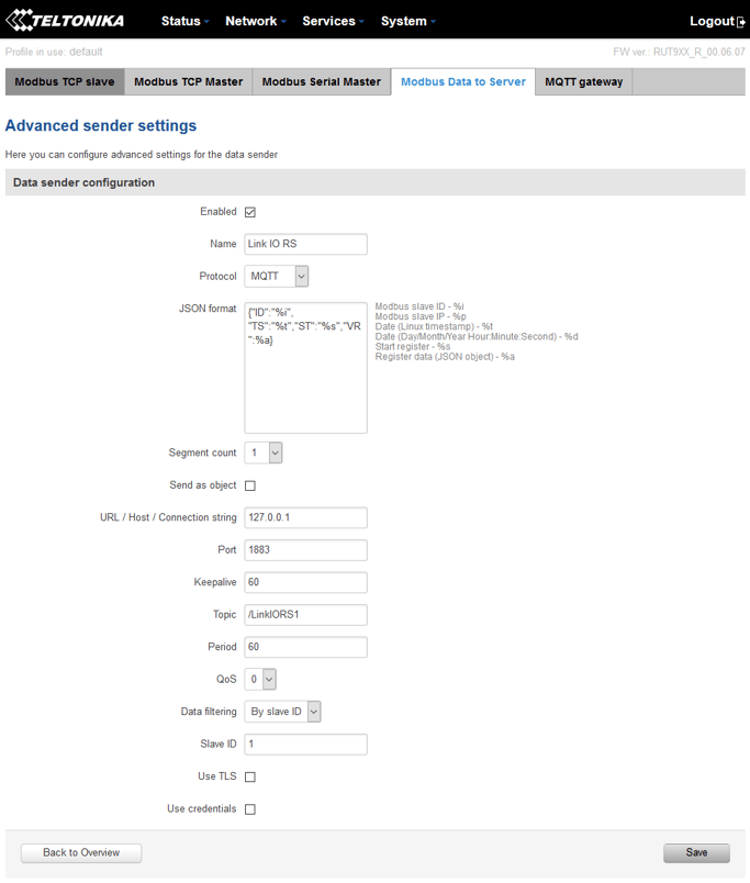
Let's have a look at how I configured the Link IO RS device to push data over MQTT here (see image below for reference)
- First thing, I give my data set a name.
- For the "Protocol" I select "MQTT".
- The JSON format comes like this by default, in case you want to change the payload. I left the default.
Please note - on later firmware versions, the JSON format field displays greyed-out examples of JSON formatting - in this case, the field is in fact blank to start with and you will need to type in the desired JSON formatting to get the MQTT publish to work
- URL/Host: this is the IP address (or URL) of the MQTT broker I want to push my data to. Because I am using the local broker, I can use the localhost IP 127.0.0.1, and the default port 1883.
- I then choose a topic where data is going to be published. It is important to organize your topics so that information is segmented properly. Topics can have a structured path like /devices/device1/data for example.
- QoS (Quality of Service) allows to retain pushed values on the broker, in case a client subscribes later and you want to have access to the data history. In my case I left QoS disabled (0).
- Data Filtering is ESSENTIAL. This is how the Modbus Data to Server function filters what data to push to the topic selected above. The available filters allow to filter by Slave Modbus ID, or by Device IP. My recommendation is to use the Slave Modbus ID if you are pushing data from RS devices through the Modbus Gateway, as they will all respond to the same IP, but have different Modbus IDs, and use the Device IP if you are pushing data from regular IP slave devices, as they should all have different IP address and often they are all set with Modbus ID 1.
This configuration should publish only the data of my Link IO RS to the local MQTT broker at topic "/LinkIORS1"
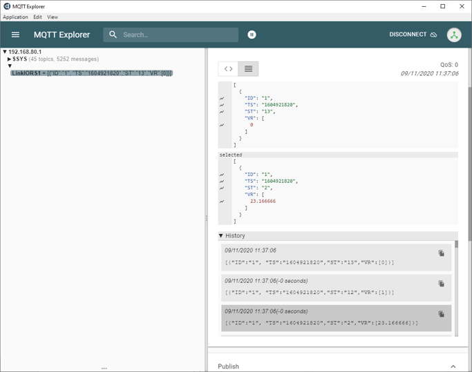
We can test this using a Windows MQTT client. I use "MQTT Explorer", available on the Microsoft store or online.
Connecting my client to the Teltonika broker, I can susbscribe to /LinkIORS1 and see all my data, being pushed every 5 seconds (the interval I configured in the Modbus Driver).
The data includes the Modbus ID, TimeStamp, StartRegister and Value, as configured on the Teltonika
Introducing the “MQTT gateway”, building Modbus commands using MQTT JSON payloads
The MQTT Gateway is an interesting feature for companies that want to have access to local network devices connected over Modbus to the Teltonika (only Modbus TCP works, or Modbus RS devices through the Gateway function enabled) using a remote MQTT client.
Note that this function is still being improved, so only a limited amount of Modbus commands are available (see the rest of the article).
The entire process starts with an MQTT client, which can package a JSON payload structured in a specific way, which allows at the end the Teltonika to "create" a Modbus command to a slave device.
The JSON payload is published to an MQTT broker, which can be either the local broker within the Teltonika, or a remote broker in the cloud.
The Modbus MQTT gateway function is then programmed to listen always to a specific topic on that broker, where the special JSON payload are expected. As soon as a new message is received, the Modbus MQTT Gateway creates the Modbus TCP Master command based on the instructions contained on the JSON payload.
The message is sent to the Modbus TCP Slave device, which then sends back a response.
The response is received by the Modbus MQTT Gateway function, which packages the response in a JSON payload.
The response JSON payload is published to a specific topic to the MQTT broker.
The MQTT client can then subscribe and receive the response in JSON and close the loop

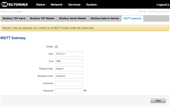
The configuration on the Teltonika is quite simple: select the broker to connect to, select the topics to subscribe to find new command and to publish to send responses, and enable the entire thing.
Modbus request data sent in the MQTT payload should be generated in accordance with the following format:
0 <COOKIE> <IP_TYPE> <IP> <PORT> <TIMEOUT> <SLAVE_ID> <MODBUS_FUNCTION> <REGISTER_NUMBER> <REGISTER_COUNT/VALUE>
Explanation:
- 0 - fixed. It signifies a textual format (currently the only one implemented).
- Cookie - a 64-bit unsigned integer in range [0..264]). A cookie is used in order to distinguish which response belongs to which request, each request and the corresponding response contain a matching cookie: a 64-bit unsigned integer.
- IP type - host IP address type. Possible values:
0 - IPv4 address;
1 - IPv6 address;
2 - hostname that will be resolved to an IP address. - IP - IP address of a Modbus TCP slave. IPv6 must be presented in full form (e.g., 2001:0db8:0000:0000:0000:8a2e:0370:7334).
- Port - port number of the Modbus TCP slave.
- Timeout - timeoutfor Modbus TCP connection, in seconds. Range [1..999].
- Slave ID - Modbus TCP slave ID. Range [1..255].
- Modbus function - Only these are supported at the moment:
3 - read holding registers;
6 - write to a single holding register;
16 - write to multiple holding registers. - Register number - number of the first register (in range [1..65536]) from which the registers will be read/written to.
- Register count/value - this value depends on the Modbus function:
3 - register count (in range [1..125]); must not exceed the boundary (first register number + register count <= 65537);
6 - register value (in range [0..65535]);
16 - register count (in range [1..123]); must not exceed the boundary (first register number + register count <= 65537); and register values separated with commas, without spaces (e.g., 1,2,3,654,21,789); there must be exactly as many values as specified (with register count); each value must be in the range of [0..65535].
Response messages
A special response message can take one of the following forms:
<COOKIE> OK - for functions 6 and 16
<COOKIE> OK <VALUE> <VALUE> <VALUE>... - for function 3, where <VALUE> <VALUE> <VALUE>... are read register values
<COOKIE> ERROR: ... - for failures, where ... is the error description
Example
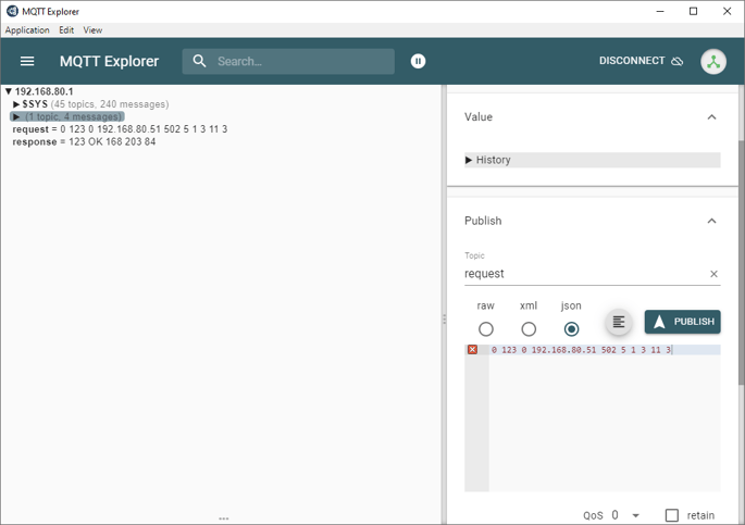
Ask a slave Jace on Modbus TCP for 3 temperatures, point addresses 10, 11 and 12 decimal. The cookie used is 123, IP of the Jace is 192.168.80.51 on port 502, timeout 5 seconds, Modbus ID 1, Modbus function 3 (read holding register), register to read is 11, number of registers to read is 3
My request in JSON will be the following:
0 123 0 192.168.80.51 502 5 1 3 11 3
And the response will look like this (values of my 3 temperatures are 16.8, 20.3 and 8.4 respectively):
123 OK 168 203 84
See here the example run using my MQTT client