How to control the WS52x via MQTT
LoRaWAN is typically used for reading data from field transmitters (sensors, meters etc), with the means of such devices transmitting "uplinks". How about communicating down to a device?
Introduction
LoRaWAN is a perfect protocol for monitoring data from field devices. The nature of the protocol and the devices that support it is to be a Long Range (LoRa), low data, low power eco system.
The field devices are typically transmitting data every few minutes, and going to a sleep state in between intervals to preserve the battery. Data is received by a LoRa gateway, which then can relay such data over LoRa again, push it over the internet to an IoT service using a dedicated connector, or pushing it over IP/internet to a receiving aggregator (like a Tridium device) via MQTT or HTTP.
The nature of the system makes it less recommended for main controls (slow data rate and potential data loss), but perfect for secondary controls such as energy optimizations and comfort improvements, controls strategies that are not going to compromise the core functionality of a system if they were not available.
There are however some LoRaWAN devices which do accept messages sent to them. Messages going to a LoRaWAN transmitters are referred to as "downlinks".
In this article we are going to use this specifically to turn the WS52x portable power socket on and off.
This article is based on the MQTT article from Milesight, which you can find HERE
The implementation we are going to use for the downlinks is by the article on Step 6, second method using the $deveui (I found it easier to implement).
Configuring the UG65
Note that in this article we are not going to explain how to add LoRa devices to the UG65, or talk about the payload decoders. If you need to know more about this part, start by checking this article HERE
The article uses HTTP as a method to transmit data, but most of the article is applicable also when using MQTT: the payload will still be a JSON payload, the setup of the sensors/transmitters is pretty much the same.
Just remember that with MQTT you will need a broker to manage your data. You can install Mosquitto on a PC, raspberry pi, or use a third party broker as preferred.
For a generic introduction to MQTT, check THIS ARTICLE
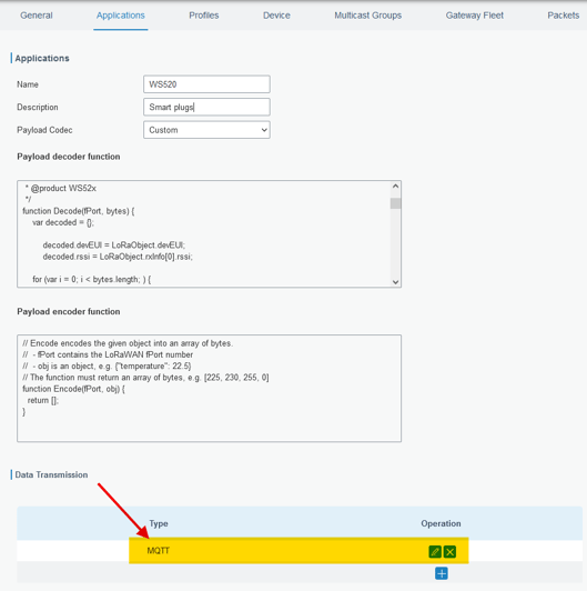
We start from the UG65 settings, by adding the MQTT data transmission on the Application associated with our WS52x

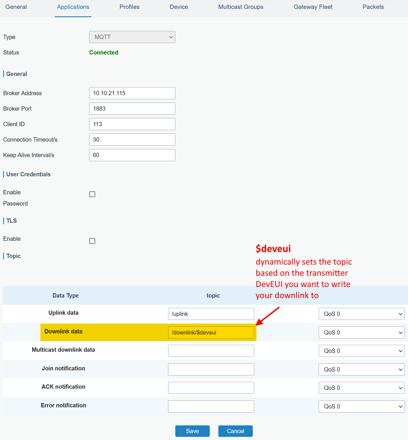
While configuring the MQTT settings, the "uplink" topic is where the system will publish all the information received by the field sensors.
The "downlink data" topic will be instead subscribed to and the UG65 is going to check it to verify your commands to be sent to the field device.
Because we use method 2 from the Milesight article, we need to add the dynamic topic part $deveui to the topic. This will make the topic dynamic, so an individual downlink topic will be available to each device using this application

Configuring the Niagara station
For the purpose of this article, we are not going through the entire setup of MQTT on Niagara.
However, we have THIS ARTICLE that can give you a full guide on how to set the standard Abstract MQTT Driver Network, which is what we also used in this example.
We added a subscribe string point called "uplinks", where all the sensor data is going to be received, and 1 publish string point called "downlinks" where the specific payloads for my WS52x are going to be published.

Note the topic containing the DevEUI of my WS52x zoomed in below:

For the "reading" part of the uplinks, you can see the result below.
You can reference these 2 articles on how to use the JSON decoding blocks, HERE using the Json Toolkit from Tridium, and HERE using the Innon Json module from us.
Note below highlighted the payload from the WS52x decoded between other sensors

As for writing the downlink payloads, we need a bit of background.
The "data" required to action the open/close command on the WS52x is the following (from the device user guide):
080100ff to switch the outlet ON (open)
080000ff to switch the outlet OFF (close)
How to we translate this into a payload for our MQTT communication?
The payload would need to be the following:
{"confirmed":[true/false],"fport":[Data Port],"data":"[Data in Base64]"}
Once we know that for our settings we need "confirmed" to be "false", data port "85", we can translate the HEX data above into BASE64, using an external tool (link THIS ONE).
The payload required to action on the digital outputs will then be as following:
{"confirmed":false,"fport":85,"data":"CAEA/w=="}
Switches ON the outlet
{"confirmed":false,"fport":85,"data":"CAAA/w=="}
Switches OFF the outlet
See here below an example of implementation I made for my test, but you can build your own strategy to send the desired payload accordingly (note, the "stringselect" has the option to start counting from 0 enabled)

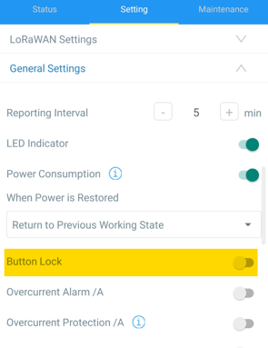
Note also that the socket has a manual on/off button on the top. Though you can create either a program object (cleaner solution) or some strategy to loop the reading to your command variable feedback slot, it might be recommended to switch off the action of the button from the configuration app, setting the Button Lock property to ON, see the property below (it is OFF in the picture)

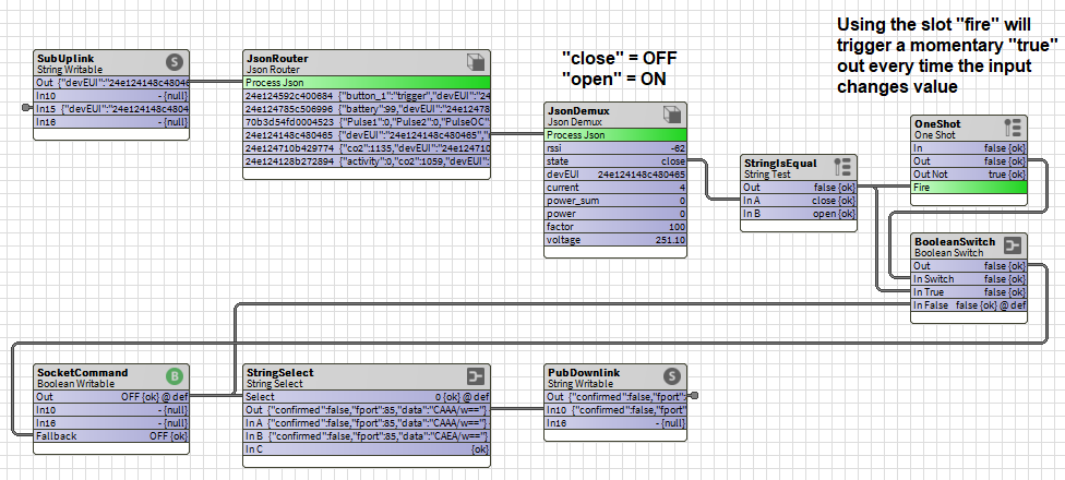
If you are still reading and are curious about a potential option on how to feedback the reading back using just blocks, here is an example that could give you some ideas

Note that the feedback reading from the button is slow being LoRa. Be patient, especially with transmission times over 5/10 minutes time.
Note (again): please use the example above as it is, an example. Modify it to your need and make sure it works for your system, as it should not be just a "copy paste" exercise.
Things to check if it doesn't work
Is the SF (Spreading Factor) setting in the sensor matching the SF setting in the Gateway Local Network Server settings (profile)?
Is the Class also the same? Sensors with batteries tend to use class A, and even if writable, they will need to be configured in Class A without adding other classes, otherwise the Local Network Server will interpret the Downlink message as a Class C message instead of A. If the sensor is powered, Class C might be needed. Please check your settings.
Is "Confirmed" being used on the sensor and did you set your payload accordingly (true/false)?
Are you using the right fport? For Milesight sensors the default is typically 85.
Did you check on the Packages section of your Local Network Server if the downlink message is getting through? If not, you might be pushing to the wrong topic or your payload has a mistake.
