Introduction
As for any network, it is really important to make sure you have the right cable and wiring to ensure the most reliable and fast communication. On RS485, we made a couple of articles about how to wire RS485 devices and the reasons behind bias and termination resistors.
With all the cables sorted, you might think that a fast baud rate (on RS485 only) and fast poll rate are the only ways to get your Modbus connectivity to be as fast and optimized as it can be. We will show you there is a much more important way to ensure your comms will work as fast as they possibly can.
Even if you don't need Modbus to be "fast", we would still recommend to keep reading, as optimizing the protocol could be useful also in case you have a really large network with lots of data being exchanged.
Covering the basics
Modbus is a simple Master-Slave protocol, and it works pretty much in the same basic way over IP or RS485: the Master always initiates the communication with a command and the Slaves provide responses to such commands.
The Master device will package the command into a series of bytes where the following information is contained:
| Slave Address |
| Function Code |
| Start Register |
| Register Count |
| Data |
| Checksum |
The addressed Slave will verify the command and respond based on the "Function Code".
The function codes are typically the following:
| Function code | Requested command |
| 1 | Read Coils |
| 2 | Read Discrete Inputs |
| 3 | Read Holding Registers |
| 4 | Read Input Registers |
| 5 | Write Single Coil |
| 6 | Write Single Holding Register |
| 15 | Write Multiple Coils |
| 16 | Write Multiple Holding Registers |
How the reading commands are processed by default on Niagara
Now, when you have a series of data point you need to read, you have different approaches you can use to get data across.
One method could be sending a reading command (1, 2, 3 or 4 according to the data type) for each individual data point, with the "Start register" being the data point address and the "Register count" being "1".
This is exactly what the Niagara Modbus driver does by default if you do not add the additional configurations we are going to see in this article.
Let see the example below:
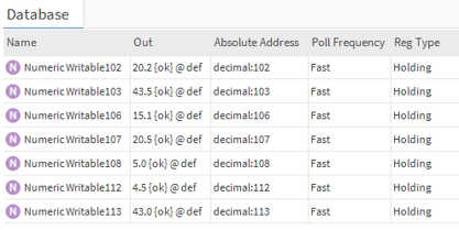
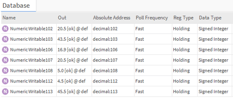
I have 7 holding registers that I am reading, address 102, 103, 106, 107, 108, 112 and 113, all configured for "fast" frequency with the default driver setting of 1 second poll rate for the fast poll frequency.
If we enable the local log for the Modbus TCP driver, we can see in our application director that the driver is sending a dedicated "read holding register" (function code "3") to each data point (in the picture below you can see 4 of the total 7 commands, reading registers 102, 103, 106 and 107):
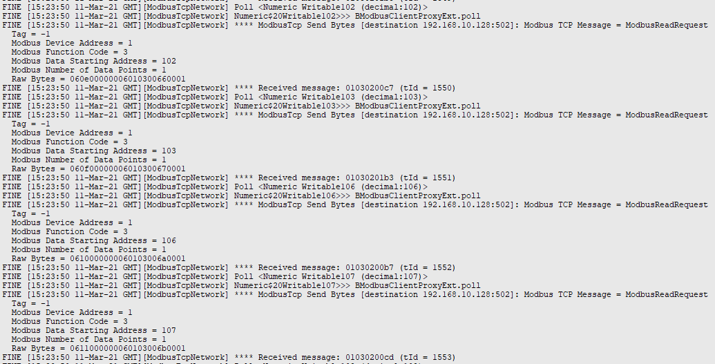
This works, but it is obviously not the most optimized way to get our data across, especially when using a large amount of connected devices and data points.
The optimization of multiple readings in general
There are methods to "condense" these commands so that they can read multiple registers at once.
Taking the example above, we could use a total of 3 commands instead of 7:
- Command 1 reading addresses 102 and 103 (start register 102, number of registers 2)
- Command 2 reading addresses 106. 107 and 108 (start register 106, number of registers 3)
- Command 3 reading addresses 112 and 113 (start register 112, number of registers 2)
This would optimize heavily the communication already.
In many cases further optimization can be achieved. The slave device might be responding to readings on registers that are not listed, and if the gap in between registers is not large, it could be more data efficient to make a reading of a larger amount of registers that includes that gap.
For example, we could read all the 7 data points by reading all the registers included between 102 and 113, with a reading command starting at register 102, number of registers 12. We would simply disregard the data we don't need (the gaps). This would make a single command a lot more efficient, with a slightly larger "data response".
How to achieve such optimization in Niagara using "Device Poll Config"
In Niagara these optimizations need to be instructed to the Modbus Driver.
This is achieved in the Property Sheet of the Modbus Slave device on the driver. The property we will be looking for is "Device Poll Config"
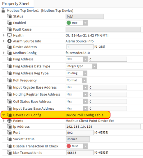
You will notice that this property by default is empty, which explains why the driver will create single reading commands for each individual data point.
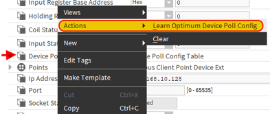
To start with, we make sure all our Modbus data points have been added to the "points" section of our Modbus device. Then, we right click on the "Device Poll Config" and we select the option "Actions - Learn Optimum Device Poll Config".
What this does is basically looking at your Modbus Data Points, find all the points that are consecutive and of the same type, and create automatically a series of instructions on the device for the Modbus Driver to read them as individual multiple register/coils (depending on the data type).
Let see the result in our simple example:
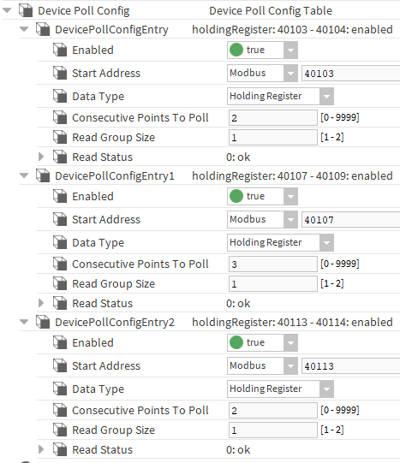
The system has created 3 commands as expected, one reading registers 102 and 103, another one reading registers 106, 107 and 108, and another one reading registers 112 and 113.
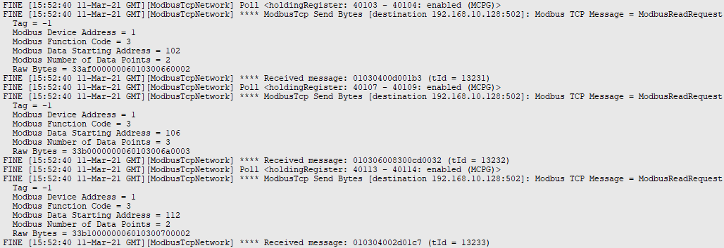
Checking the fine details on the application director for the Modbus TCP driver, I can see clearly the 3 optimized commands now instead of the 7 commands I had before:
Of course the configuration can be done manually and can be edited as well.
Let's transform the Device Poll Config into a single command that reads all the registers between 102 and 113. Niagara will take only the data that has been added as a "data point" and disregard automatically any other data read in between (the gaps).
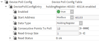
I can right click on 2 of the automatically defined Poll Configurations and delete them, then modify the remaining one to read from register 102 a total of 12 registers (the ones I need and all the gaps):
Looking now at the application director, the only command I see is this
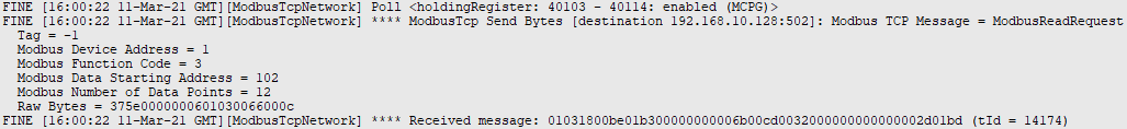
And all my points are reading in the best optimized way
Important note: A Modbus message can’t exceed 256 bytes. So the maximum number of registers that can be read in a single command is 125. Check the device you are connecting to with the manufacturer, as it might have specific further limitations to this figure.